2: Drawing an Escape Wheel
I am currently using an IBM with Windows and a drawing program called
KeyDraw. If you have AutoCAD, you are well equipped. The most important features
you need are the ability to draw lines and circles on a grid, and the ability to rotate the
lines by angles that you determine. You may have a different method. This is just one
way to do it.
First, draw a
large circle. A diameter of 6 inches worked well for me. Draw another circle of 4.5 inch
diameter and center it inside the first. Draw a horizontal line across this circle, bisecting
it. Draw a tooth on one side until you are satisfied: I chose a line at 15º and another at 25º
from horizontal, positioned to fit, and with a small gap to allow for tooth thickness.
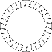
Duplicate, rotate, and place a tooth on the other side. Remove the line and mark the center of the circle. Your drawing should look like
this.
 |
Move the
inner circle outside. Group the outer circle with the line and the two teeth, duplicate
and rotate by 12º. Duplicate the new group and rotate it by 12º again. Repeat this until
you have thirty teeth. Ungroup all the elements and remove the outer circles, one at a
time, until only one is left. Place the inner circle in its original position, and group all
the teeth and circles. The reason for placing a tooth in a circle before rotating is
because the circle makes the tooth rotate about the center of the circle, in order to
achieve the desired result.
 |
Rotate the groups by 12º at a time because there are 360º in a full circle, so if you
want a 30 tooth circle: 360 / 30 = 12º. If you want a 48 tooth circle, divide 360 by 48 to
get 7.5º. Thus escape wheels with different numbers of teeth could easily be made.
Escape wheels with the teeth pointing in the other direction could be made by flipping
the image, or with teeth of different shapes, such as the club-tooth escape wheel in Swiss
watches.
Table of Contents
Escapements in Motion
Clock Repair Main Page
Links Page