 |
The first four photos show a 9-tube Herschede #2 grandfather clock mechanism (circa 1980) as it was disassembled. The mechanism is similar in many ways to traditional designs of high-grade tubular bell grandfather clocks. Every effort should be made during repairs to avoid damaging the lacquered finish of these magnificent clocks. Click on the images below to see enlargements. This is probably the most impressive example of a modern Herschede I have seen. The dial is stunning!
 |
Fig. 1
 |
Fig. 2
 |
Fig. 3
 |
Fig. 4
The following photos show a 5-tube Herschede grandfather clock (circa 1956) as it was repaired. This clock was sent from Jamestown, NC. The 5-tube serves as a better example to show the adjustments that need to be made because Figures 9, 12 and 14 would be difficult to photograph with the 9-tube clock above. An entire website could be written about this clock, so this page is only an introduction. All clocks with lacquered plates, including this one, should be cleaned by hand with a mild cleaner. I used a cloth with alcohol. Figure 5 shows what happened to the finish when this clock was once cleaned with an aggressive solvent: much of the lacquer was removed.
 |
Fig. 5
After replacing worn bushings, polishing pivots and doing any other necessary repairs, the gears are arranged on the front plate, as shown in figure 6. The pivots of the first three wheels for the chime and strike trains and the first two wheels for the time train are lubricated with graphite grease before assembly. The bushings for those wheels are also lubricated with graphite grease before assembly.
 |
Fig. 6
Figure 7 shows that the pinion gear for the escape wheel is next to the front plate. Since the second hand is mounted to the escape wheel, the weight of the second hand and the torque applied to the pinion both result in unusual wear of the bushing for the escape wheel on the front plate. I recommend that this bushing should always be replaced when servicing any clock with this design (this is true of many Herschede, Elliott and Western Union Self-Winding clocks).
 |
Fig. 7
The parts of the chime train need to be adjusted after assembly. Find the position that makes it possible to mount the gathering pallet most easily (since the square on the third wheel is probably not perfectly square). Place the chime lift lever, the chime rack and the rack hook in their respective positions, as shown in figure 8.
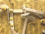 |
Fig. 8
With the gathering pallet tail resting against the rack pin (Figure 8), the pin on the fourth wheel (or warning wheel) should be at 90ş from vertical, towards the right side, as shown in Figure 9. It is often necessary to pry the plates apart slightly to change the relationship between the gears in order to achieve this. The result is that the warning wheel rotates by about a quarter turn when the gathering pallet tail is released and the chimes go into warning.
 |
Fig. 9
The procedure has two steps for the strike side. The arrangement of the gathering pallet, the rack and the rack hook is the same as for the chimes. Notice in Figure 10 that someone attempted to repair the rack and the rack hook by filing a deeper locking face on the rack. This should NOT be attempted by anyone who does not understand the proper relationship of these parts (read the strike rack repair essay on this website).
 |
Fig. 10
With the gathering pallet tail resting against the rack pin (Figure 10), a pin on the second wheel should have just released the strike hammer lever, so that the strike hammer will have just dropped. This is shown in Figure 11. It will probably be necessary to pry the plates apart slightly to arrange the strike gears in order to achieve this.
 |
Fig. 11
The pin on the fourth wheel (or warning wheel) should be at 90ş from vertical, towards the left side, as shown in Figure 12. You may need to pry the plates apart yet again. The warning wheel will rotate by about a quarter turn when the strike goes into warning.
 |
Fig. 12
The assembly of this clock is almost complete as shown in Figure 13. The cables need to be installed. The escapement pallets also need to be installed. With the chime gathering pallet resting against the rack pin, the chime drum needs to be adjusted as follows. There are five hammers (1-2-3-4-5, from right to left, when looking at Figure 13). The drum should be positioned such that the hammers have been lifted in the sequence 1-2-3-4, and the fourth hammer has just been released.
 |
Fig. 13
The depthing of the gears on the vertical shaft (see Figure 14) is very important. Particular attention should be paid here. Depthing is explained in the essays about gearing on this website.
 |
Fig. 14
The photo in Figure 15 came from the internet. I present it to show you a Herschede five-tubular bell mechanism with two weights (instead of three). If you see a clock for sale with this mechanism, do not buy it. Look for a mechanism with three weights instead. As a general rule, any clock with quarter-hour chimes, like the Westminster chime, and two weights or two mainsprings, should be avoided.
 |
Fig. 15
Here is a Herschede #1 movement from 1922, their top of the line and considerably larger than the Herschede #2 at the top of this page. This clock was badly abused and sold for parts on Ebay. It looked clean but several parts were corroded, so the chimes and strike did not work correctly, requiring a lot of repairs. The case arrived two months later from Chicago.
 |
Fig. 16
However, the dial, the case, the pendulum and the weights had all been refinished, probably recently, so the end result was stunning.
 |
Fig. 17
This story has a happy ending because a magnificent Herschede was saved from the parts heap. Having two is even better!
 |
Fig. 18
Clock Repair Main Page
Escapements in Motion
Links Page