Western Union Clock
The Self-Winding clock is a mechanical clock with a mainspring and a pendulum. What makes it different from other clocks is an electric motor under the mechanism that winds the mainspring by one revolution every hour. Two large 1.5-volt batteries in the clock case power the motor. Figure 1 shows the small mainspring, mounted inside a cage on the center wheel.
 |
Fig. 1
When reassembling the parts on the center wheel, wind the mainspring by four turns and assemble the parts as shown in Figure 2.
 |
Fig. 2
There are fewer parts in this clock than in many others. Note the cam on the center wheel in Figure 3. In front of the center wheel is a ratchet wheel with many small teeth. On the left side is the detent click. On the right side is the driver click, which is linked to the motor arm.
 |
Fig. 3
Figure 4 shows a front view of the clock after assembly. The canon pinion, the minute wheel and the hour wheel have been attached.
 |
Fig. 4
The clock becomes more complicated when the second motor is added to the side of the clock. The purpose of the second motor was to reset the minute hand and the second hand to zero when the second motor received a signal and was activated by the Naval Observatory once a day. This service cost $25 in the 1930s, which included leasing the clock itself. Many of these clocks were leased to the Western Union Company. This service is no longer available for these clocks, but the parts are assembled the way they were to keep the clock all-original.
  |
Fig. 5
The cam on the center wheel pushes a contact up against another contact, shown in Figure 6, once every hour. The motor has current flowing through its coils, which activates its magnets.
 |
Fig. 6
Figure 7 shows the motor arm. The left photo shows the arm in the resting position. When current flows through the coils, the magnets attract the arm, pulling it up, as shown in the right photo. When the arm is up, it pushes against a contact, separating it from another contact, which interrupts the current flow. This allows the arm to fall again and the contacts touch again, enabling the current to flow, so the arm is pulled up again. This clock has another pair of contacts on the other side. Both pairs of contacts are activated simultaneously by the movements of the motor arm.
  |
Fig. 7
Figure 8 shows a resistor that is connected at both ends of the coils. The resistor has a resistance of about sixty ohms and its purpose is to prevent arcs between the contacts (Figure 7), which can be seen as little blue sparks in the dark. The arcs would cause corrosion of the contacts. The resistor in Figure 8 is obviously original!
 |
Fig. 8
As the motor arm moves up and down, vibrating rapidly, it causes the click under the ratchet wheel in Figure 9 to vibrate rapidly, causing the ratchet wheel to rotate, winding the mainspring until a pin in the center wheel pushes the cam out of the way and allows the contacts in Figure 6 to separate. The mainspring has been wound by one turn and the clock will run for another hour before the cam on the center wheel will cause the winding process to be repeated. The other click (above the ratchet wheel, on the left side) prevents the ratchet wheel from rotating in the opposite direction.
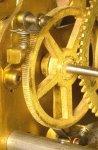 |
Fig. 9
The Graham escapement with an unusual sixty-tooth escape wheel is shown in Figure 10. Few escape wheels have so many teeth. The result is that the pallets and the teeth must be relatively thin. (A Self-Winding clock with a one-second pendulum has thicker pallets and an escape wheel with thirty teeth, but all other parts are interchangeable.)
 |
Fig. 10
The case has the pendulum mounted onto it, shown in Figure 11. There is an old battery on the left side (the one on the right is missing). Since these batteries are not available, I added two new wires to the mechanism and connected a three-volt transformer with a six hundred milliamp capability. Anyone who wants to remove the transformer and run the clock on batteries can do so by putting the old wires the way they were, since none of the original wires were removed.
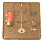 |
Fig. 11
The mechanism is screwed onto the case in Figure 12.
 |
Fig. 12
The dial and the hands are attached to the mechanism and the cover has been placed over the case in Figure 13.
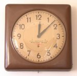 |
Fig. 13
These clocks are very accurate even without the daily time signal from the Naval Observatory! The unusual design of the pendulum bob was deliberate, in order to make it temperature compensating, which, combined with a virtually constant driving force, results in excellent timekeeping (compared with other pendulum clocks). Even better timekeeping can be achieved with a mercury pendulum, which a few of the larger Self-Winding clocks had. These clocks were built to last for generations!
The clock in Figure 14 offers another example of a virtually constant driving force because the mainspring is wound every eight minutes by an electric motor. This is a battery clock by GE from around 1965. It has a lower grade balance wheel and pin pallet escapement, like those found in typical thirty hour alarm clocks of that era. Whereas those alarm clocks kept time to about two or three minutes per day, the virtually constant driving force of the mainspring enabled this GE clock to keep time to about ninety seconds in two months!
 |
Fig. 14
Clock Repair Main Page
Escapements in Motion
Links Page